No products in the cart.
Return To ShopCommon Problems With Microhardness Testing
Microhardness testing is a method of determining a material’s hardness or resistance to penetration when test samples are small, thin, or dealing with composite samples in small regions. Microhardness testing can provide precise and detailed information about surface features of materials that have a fine microstructure. However, there are some common problems that can arise when microhardness testing. We are going to go over common problems with microhardness testing, and their causes.
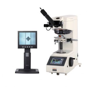
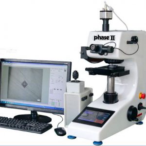
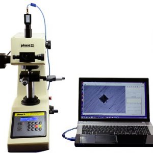
For a lot of engineers, scientists, and testers, three terms often come into their minds when talking about microhardness testing: finicky, subjective, and time-consuming. Now, advances in computer technology have reduced the reasons these terms come to mind. Microhardness testers are advanced instruments where extremely light forces (typically from 10 –1,000 g.) must be accurately applied, and the resultant impressions must be precisely measured under high magnification. Because of these tight needs, some common problems do arise.
Common Problems with Microhardness Testing
There are three basic problems that arise when microhardness testing.
- Accuracy – The ability of the instrument to read in linear fashion on recognized hardness standards (certified test blocks), and its ability to transfer this accuracy onto test specimens.
- Repeatability- Can the results be duplicated using recognized hardness standards.
- Correlation – Can two properly calibrated machines or two operators come up with the same or similar results (not to be confused with repeatability where that would be using the same machine, and same operator.
Causes for These Basic Problems
The Machine.
Vickers Microhardness testers creates measurements by using dead weights to create force. These light loading devices (10-2,000 gf) stack the dead weights directly on top of the indenter. Though this eliminates the error of magnification as well as other errors, this can cause repeatability issues. In most cases, the microhardness machine applies the load application using two speeds — a “fast speed” to bring the indenter close to the test piece, and a “slow” speed to contact the work and apply the load. The “stroke” of the indenter is usually set with a measuring device. Altogether, it takes approximately 30 seconds for an instrument to make an impression. In that time, the alignment of the indenter with the objectives is critical when taking depth measurements or just trying to accurately place an impression on a specific spot. Get this part wrong, and even thought the hardness value is not affected, the distance from the edge of the sample may be wrong and ultimately result in an erroneous measurement.
The Operator.
Microhardness testing is significantly influenced by the abilities and skills of the operator. Proper focus is a critical factor in achieving accurate results. It is extremely easy to misread or misinterpret blurry images and results. In many cases, operators are sometimes rushed to perform tests and get parts out the door. Care must be taken to ensure the proper results. In many cases, automated focusing of the machine can help eliminate some of the perception error brought on by tedious, laborious, and repetitive tasks.
Recording and converting results manually can be another cause for error by the operator. It is very easy for tired eyes to see 99.3 as 9.93. Digital microhardness testers that automatically give conversions and results can help eliminate this issue. Also, cameras can be attached to virtually any microhardness tester, in order to help find impression ends.
Environmental Issues.
Due to light loads utilized in microhardness testing, vibration can be a contributor to loading accuracy. The oscillation of the indenter or the test specimen can cause the indenter to work its way deeper into the part, creating a softer result. Microhardness testers should always be placed on a dedicated, level, sturdy, table that is free standing. Make sure your table is not against a wall or adjoining table.
Microhardness hardness tester machines have high-power optical lenses. If you cut, grind or polish near the tester, you could get dirt on the lens causing an inaccurate result.
Sample Preparation
In most cases, samples are sectioned and mounted in bakelite or epoxy mounts prior to testing. Once sectioned and mounted, the samples are ground, sanded, and polished to provide a test surface that is free of scratches and surface texture that could otherwise interfere with the operator’s ability to discern the tips of the impression.
Yet, there are times in production environments that do not allow the proper time to prep the sample, so the sample is rushed. Rushing the sample can result in undulating surfaces, rounded edges that are difficult to discern, and surface imperfections that make it difficult to accurately measure the tips of the impression.
Etching samples can provide metallographic contrast helping define grain structure. However, heat affected zones in welds, total case depths, and decarb layers, it lessens the contrast between the test surface and the tips of the microhardness impressions. This can create difficulty or the total inability to measure the impression.
Calibration.
Calibration is actually an exceedingly rare issue. This is because most microhardness testers are kept in a laboratory instead of the field. Regardless though, microhardness testers are dependent upon being at a specific magnification, or distance (the ocular slides in/out to increase/decrease magnification) from the objective. To directly verify the measuring system, a stage micrometer is placed on the anvil, and the instrument’s measuring lines are placed at a known distance on the stage micrometer. This distance is then compared to the unit’s measuring system. If they agree, all is well. If not, the ocular is moved in/out to increase/decrease the measuring distance. If you are not careful of the ocular position, the measuring accuracy can be compromised. Microhardness testers are usually indirectly verified against Standard Hardness Blocks. This means, though, that improperly handled test blocks can cause a miscalibration.
It is easy to have one issue compound on another. A tired operator using a machine set against a wall can lead to completely wrong results and cause all sorts of issues in production. The use of digital machines will help eliminate some issues, but it’s best to guard against others so the right results occur.
Metallurgical Supply Company (METSUCO) has been a leading supplier of hardness testing machines and blocks for over 30 years. We serve not only industries such as oil and gas, aerospace, automotive, and heavy manufacturing, but also universities and quality testing labs. Call 713-827-0700 or email sales@metsuco.com with inquiries.

